Controlling a single-phase air compressor requires the use of a specific wiring diagram – one tailored to that type of compressor. Although this diagram is far less intricate than the diagrams used in three-phase compressors, which generally control industrial machinery, it contains all necessary info to ensure the compressor runs smoothly and securely.
With its ability to compress air, a single-phase air compressor is an essential tool in the commercial and industrial sector. Constructed from a stator, rotor, an assortment of contactors, pressure switches, overloads, and other electronics, the electric motor is the heart of this machine – however to ensure harmony between all components it must be correctly connected to a power source.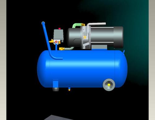
It is essential to adhere to the manufacturer’s instructions when wiring up a single-phase air compressor. This necessitates the use of appropriate sized wires and insulation, as well as proper component synchronization. The wiring diagram should showcase the connections of the pieces, plus the hues of the cables.
Various components are required in order to construct a single-phase air compressor wiring diagram, such as the power source, contactors, overloads, pressure switches, and other elements integral to the overall plan.
Ensuring the efficiency and durability of a compressor involves making sure it has a dependable power source. This is typically a 240-volt single-phase wiring, and must be securely connected to guarantee that the compressor carries out its function correctly. To regulate the air pressure, pressure switches are employed, and contactors are used to switch the compressor on and off. Additionally, overloads guarantee that the machine doesn’t become strained or overworked, and remain in its peak condition.
When connecting the power source to a single-phase air compressor, one must heed the manufacturer’s instructions and use electrical components of correct size and insulation. The wiring should follow the details of the diagram provided.
The electricity must be linked to the contactors and overload protections using the appropriate wiring diagram. The contactors must be wired complying to the indicated scheme while the overloads should be firmly connected to the power source and its related contactors. To finish, the pressure switches needs to be attached to the contactors.
When working on a single-phase air compressor, it’s essential to adhere to safe practices. Make sure the components are connected properly and the wiring is up to standard. Shield the cabling with suitable insulation, and safeguard exposed electrical wires with measures for covering them. Additionally, double-check that all components are certified for the applicable voltage level before continuing with the job.
Adhering to a single-phase air compressor wiring diagram is necessary for guaranteeing the safe and efficient operation of the device. After all, this diagram supplies the vital information for properly wiring the compressor. To make sure everything is connected correctly, understanding any manufacturer guidelines and selecting the ideal wire size and insulation is crucial. Additionally, all safety precautions must be taken into account when working on the wiring.
In order to ensure a safe and efficient operation of an air compressor, it is essential to understand the wiring diagram that outlines how the compressor ought to be connected to an electrical power source. As these devices are used in a wide range of contexts, from domestic to commercial, a single phase air compressor wiring diagram offers an invaluable tool to anyone installing or servicing the appliance. The diagram allows for a more informed approach to dealing with the machine’s wiring so that no issues arise.
Setting Up Your Single-Phase Compressor: A Guide.
Electrical diagrams detail the connections needed to energize a single phase air compressor. Visually, they portray the electricity source, the compressor itself, and its associated wiring. Safety components found in the system are also identified. Additionally an illustration of power flow shows how connections direct electricity while switches are depicted for control purposes.
Before beginning any wiring for a single phase air compressor, it is absolutely critical to ensure that all aspects of safety are properly taken into consideration. The power source should be immediately switched off; this acts as a precautionary measure to guarantee that no electricity will be present during the wiring process. Furthermore, all components should be delicately grounded in order to protect against any possible shocks or unfortunate fires.
A compressor’s wiring diagram typically includes two sections – the electricity source and the compressor itself. Regular single-phase residential power outlets supply the power source needed for the compressor, though if three-phase electricity is needed then the wiring needs to be adjusted accordingly.
To produce the pressurized air necessary for a variety of uses, an air compressor is employed. This tool typically consists of a motor, a compressor head, and a tank. The motor acts as a catalyst, powering the compressor head to reduce the volume of air entering. The tank then stores this condensed air for future use.
Outfitting a Single-Phase Air Compressor – An Overview
In order to wire a single phase air compressor correctly, it is essential to follow the instructions laid out in the wiring diagram. Generally, this diagram will comprise two principal sections; the power source and the actual compressor. In most instances, this power source will be a single-phase electric system such as an average household outlet.
To start wiring your compressor, the first step is to join the power source to the compressor motor. Most often, this is done with a three-wire cable. The black wire from the power source will correspond to the breaker, the white wire will be for the neutral line, and the green wire is used as a ground. Before attaching the power source to your compressor, make sure to feed it through a circuit breaker.
With the power source connected, the wiring step is next. The black wire should be linked to the motor terminal, followed by the white wire being fastened to the neutral terminal, and finally, securely affixing the green wire to the ground terminal.
To complete the setup, the pressure switch should be fastened to the compressor via a two-wire cable. The black wire needs to be linked to the power source while the blue one must be securely fastened to the motor terminal of the compressor.
Utilizing a screwdriver, adjust the pressure switch to its reserved pressure level once the wiring process wraps up. The precise setting can be unearthed in the compressor’s accompanying handbook.
A wiring diagram for a single phase air compressor is an absolute must-have when it comes to setting up or tending to an air compressor. These diagrams reveal how the power source and pressure switch are hooked up to the compressor; thus, following their instructions is indispensable for a secure and efficient operation of the compressor.
Post time: 2023-08-01Related Product
Warning: Use of undefined constant rand - assumed 'rand' (this will throw an Error in a future version of PHP) in /www/wwwroot/www.sunritamachinery.com/wp-content/themes/msk5/single.php on line 69
S250 Air Leg Pneumatic Rock Drill Pusher Leg Rock Drill
Product description: (S250 jackleg Drill) has been the preferred choice of miners who demand high performance, superior control and lasting reliability. the S250 jackleg allows ope […]
S82 Air Leg Pneumatic Rock Drill Pusher Leg Rock Drill
Scope of application: Model S82 air-legged rock drills are heavy-duty air-legged rock drills with high efficiency and low consumption, which are especially suitable for use in the […]
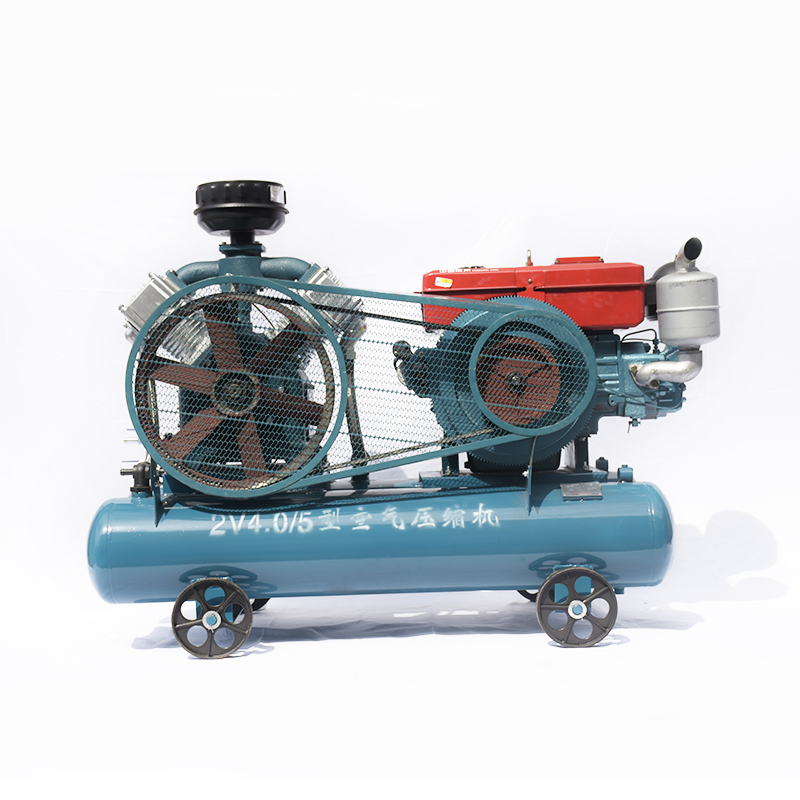
20KW Mining Diesel Piston Air Compressor 2V4.0-5
Double Air Tank Diesel Portable Best-Selling Engine Oil Piston Air Compressor are mainly used to supply stable and clean compressed air to the pneumatic tools and keep them working […]
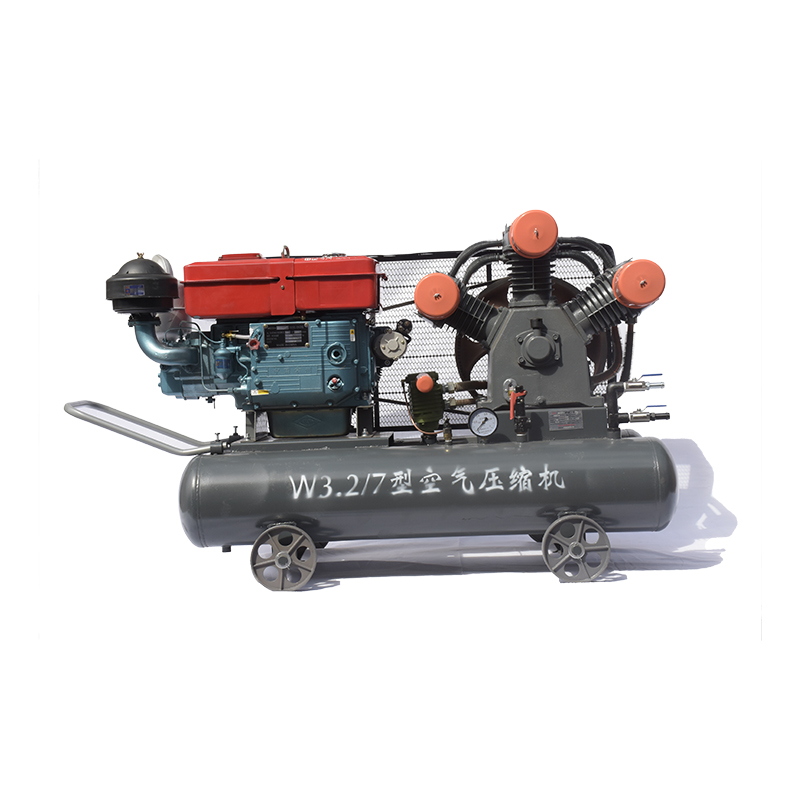
20KW Mining Diesel Piston Air Compressor W3.2-7
Advantages Small in size,light in weight, easy to move Top material and superior technology Simple structure, high efficiency, good performance, and low price Adopt the most popula […]
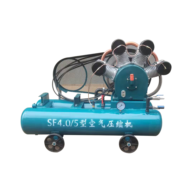
20KW Mining Diesel Piston Air Compressor SF4.0-5
Advantages Small in size,light in weight, easy to move Top material and superior technology Simple structure, high efficiency, good performance, and low price Adopt the most popula […]

TCD20 Pneumatic Pick Air Shovel Cement Crusher Pneumatic Chipping Hammer
Product description: The TCD-20 pneumatic pick is powered by compressed air using Japan’s TOKU technology Crushing tools, features: lightweight, small size, large strike ener […]
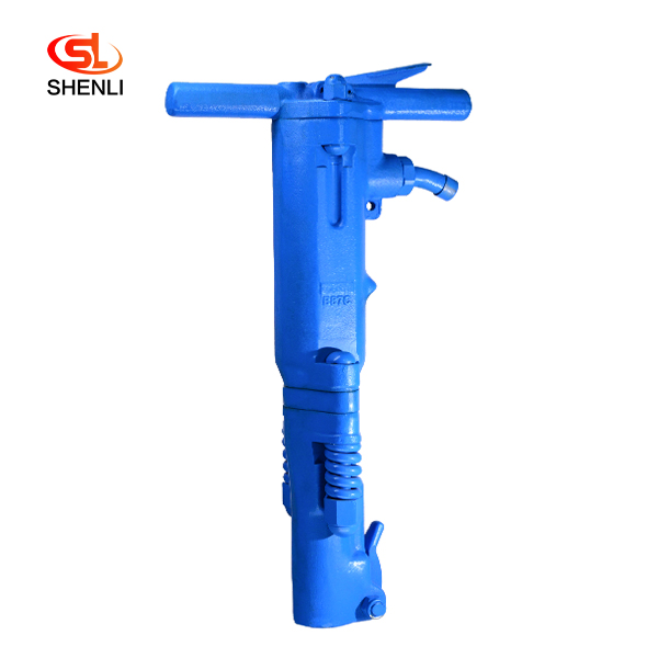
B87C Pneumatic Pick Air Shovel Cement Crusher
Product Description: The B87C crusher is made from Canada. Denver pneumatic Group company mature technology, with compressed air as a power crushing tool, can efficiently complete […]

TPB6 Air Concrete Breaker Pneumatic Pick
Product introduction: TPB-60 crusher adopts the mature technology of TOKU Group, Is compressed air as the power of the crushing tool, can efficiently complete the reinforced concre […]
18.5KW Mining Diesel Piston Air Compressor W3.0-5
Advantages Small in size,light in weight, easy to move Top material and superior technology Simple structure, high efficiency, good performance, and low price Adopt the most popula […]